• Choosing Solar Panels The Three Key Types You Need to Know

    Choosing the right solar panel is a critical step toward achieving energy independence and sustainability. Whether you’re a homeowner or a business, understanding the strengths and limitations of each solar panel type will help you make the most informed decision for your energy needs.


    The Basics of Solar Panel Types

    Solar panels are primarily divided into three types: Monocrystalline Silicon Solar Panels, Polycrystalline Silicon Solar Panels, and Thin-Film Solar Panels. Each type has its own unique features, pros and cons, and ideal use cases. Understanding these characteristics will help you make an informed decision.


    1. Monocrystalline Silicon Solar Panels

    Features

    Monocrystalline silicon solar panels are made from high-purity silicon wafers and offer very high efficiency and durability. They typically have a black appearance and round or rounded-edge rectangular shapes, making them popular for their high energy conversion rates.


    Advantages

    High Efficiency: Monocrystalline panels typically have an efficiency range of 18% to 22%, making them ideal for installations with limited space.

    Long Durability: These panels have a long lifespan, often lasting 25 years or more.

    Ideal for High-Demand Applications: They perform especially well in sunny regions, providing higher energy output.


    Disadvantages

    Higher Cost: Due to their complex manufacturing process, monocrystalline panels tend to be more expensive, making them more suitable for those with a larger budget.


    Best Use Cases

    Monocrystalline panels, such as the Full Black N-Type Solar Panel options, are perfect for residential, commercial, and industrial applications, especially for users with higher energy demands or limited installation space. They offer an ideal solution for those seeking efficient and long-lasting solar energy.


    2. Polycrystalline Silicon Solar Panels

    Features

    Polycrystalline silicon solar panels are made from multiple silicon crystals and usually have a blue appearance. While they are slightly less efficient than monocrystalline panels, they offer a cost-effective alternative.


    Advantages

    Lower Cost: The manufacturing process for polycrystalline panels is simpler, making them more affordable.

    Good Stability: While their efficiency is slightly lower, they still provide reliable energy output in most applications.


    Disadvantages

    Lower Efficiency: Polycrystalline panels typically have an efficiency range of 15% to 18%, which means you may need a larger area for the same energy output.

    Shorter Lifespan: Polycrystalline panels generally have a shorter lifespan compared to monocrystalline panels.


    Best Use Cases

    Polycrystalline panels are ideal for homeowners or small to medium-sized businesses on a budget, especially when larger installation spaces are available. They provide a cost-effective solar energy solution.


    3. Thin-Film Solar Panels

    Features

    Thin-film solar panels are made from thin layers of semiconductor materials and can be applied to various surfaces, including curved or irregular surfaces. They generally have lower efficiency but offer flexibility in large-scale installations.


    Advantages

    High Flexibility: Thin-film panels can be applied to different surfaces, making them suitable for irregular or curved areas.

    Low Cost: Thin-film panels are usually cheaper to produce due to the simpler manufacturing process.

    Lightweight: These panels are lightweight, which makes them easy to transport and install.


    Disadvantages

    Lower Efficiency: Thin-film solar panels usually have an efficiency range of 10% to 12%, so they require more installation space to generate the same amount of power.

    Shorter Lifespan: Compared to other types, thin-film panels have a shorter lifespan, typically around 10 to 15 years.


    Best Use Cases

    Thin-film panels are best suited for large-scale commercial projects or solar farms, where space is not a constraint. They are also ideal for situations where aesthetics are less important.


    How to Choose the Right Solar Panel for Your Needs

    When selecting a solar panel, consider the following factors:

    Budget

    If you have a higher budget and want high efficiency and long lifespan, monocrystalline panels are the best choice. However, if you are on a tighter budget, polycrystalline or thin-film panels can provide a more cost-effective option.


    Installation Space

    If you have limited roof space or installation area, monocrystalline panels, like the Full Black N-Type Solar Panel, are a great choice due to their higher efficiency. On the other hand, if you have a larger space, polycrystalline or thin-film panels can offer a more economical solution.


    Geographical Location

    If you live in an area with abundant sunlight, monocrystalline panels will maximize energy production. In regions with more balanced sunlight conditions, polycrystalline or thin-film panels will still perform reliably.


    Long-Term Return on Investment

    While monocrystalline panels are more expensive upfront, their higher efficiency and longer lifespan make them a worthwhile long-term investment. If you plan to use your system for over 25 years, monocrystalline panels, such as Full Back Bifacial 440W Solar Panel, are a smart choice.


    Choosing the right solar panel is a critical step toward achieving energy independence and sustainability. Whether you’re a homeowner or a business, understanding the strengths and limitations of each solar panel type will help you make the most informed decision for your energy needs.


    Enecell’s all-black monocrystalline solar panels are crafted with cutting-edge technology and premium materials to deliver superior performance and long-lasting durability. With a 25-year power warranty, our panels ensure reliable energy production for years to come.

  • Green Hydrogen Production Why Alkaline Electrolyzers Are Leading the Market

    Introduction

    As the world shifts toward renewable energy, green hydrogen—produced using electrolysis powered by clean electricity—has emerged as a key player in decarbonizing industries like transportation, steelmaking, and chemicals. Among the different electrolyzer technologies, alkaline electrolyzers (ALK) currently dominate the market. But why?

    In this blog, we’ll explore the advantages of alkaline electrolyzers, their role in green hydrogen production, and why they remain the preferred choice for large-scale projects.


    What Are Alkaline Electrolyzers?

    Alkaline electrolyzers have been around for decades and are one of the most mature technologies for hydrogen production. They use an alkaline solution (typically potassium hydroxide, KOH) as an electrolyte and nickel-based electrodes to split water (H₂O) into hydrogen (H₂) and oxygen (O₂) through an electrochemical reaction.

    Key Reaction:

    At the cathode: 2H₂O + 2e⁻ → H₂ + 2OH⁻
    At the anode: 2OH⁻ → ½O₂ + H₂O + 2e⁻


    Why Alkaline Electrolyzers Dominate the Market

    1. Proven Technology & Reliability

    Alkaline electrolyzers have been used for industrial hydrogen production since the early 20th century. Their long track record makes them a low-risk choice for large-scale projects compared to newer technologies like PEM (Proton Exchange Membrane) or SOEC (Solid Oxide Electrolyzers).

    2. Lower Capital Costs

    One of the biggest advantages of ALK systems is their cost-effectiveness. They use non-precious metals (e.g., nickel instead of platinum or iridium), making them significantly cheaper than PEM electrolyzers, which rely on expensive catalysts.

    3. Scalability for Industrial Use

    Alkaline electrolyzers are ideal for large-scale hydrogen production, such as ammonia plants or refineries.

    4. Longer Lifespan & Durability

    With fewer degradation issues than PEM systems, ALKs often have lifespans about 20 years, reducing long-term operational costs. Their robust construction makes them suitable for harsh industrial environments.

    5. Compatibility with Renewable Energy

    While ALKs traditionally required stable power inputs, advancements in dynamic operation have improved their ability to work with intermittent renewable sources like wind and solar.


    Challenges & Future Improvements

    Despite their advantages, alkaline electrolyzers face some limitations:

    Lower Efficiency at Partial Loads – They perform best at steady, high-capacity operation.

    Slower Response Times – Less flexible than PEM electrolyzers for rapid start-stop cycles.

    Liquid Electrolyte Maintenance – Requires periodic refilling and corrosion management.


    However, innovations such as:
    Advanced electrode materials (improving efficiency)
    Zero-gap configurations (reducing energy losses)
    Hybrid systems (ALK + PEM)
    are helping ALKs stay competitive.


    Conclusion: Alkaline Electrolyzers Lead the Green Hydrogen Race

    While newer electrolyzer technologies are gaining attention, alkaline electrolyzers remain the market leader due to their cost efficiency, scalability, and proven reliability. As green hydrogen demand grows, ALKs will continue playing a crucial role in the energy transition—especially for large industrial applications.

    For now, they are the go-to solution for cost-effective, large-scale green hydrogen production.

  • Understanding Energy Storage Systems and Their Efficiency

    In recent years, as the world gradually shifts towards renewable energy sources like solar and wind power, energy storage systems have become increasingly important. These systems are used to store energy for later use, ensuring a reliable and continuous power supply even when sunlight or wind is insufficient. So, what exactly is an energy storage system, what is the best method for storing energy, and which is the most efficient? Let's explore these questions.


    What is an Energy Storage System?

    An Energy Storage System (ESS) is a device or technology used to store energy for later use. It works by converting electrical energy into a form that can be stored (such as chemical energy, mechanical energy, or thermal energy), and then converting it back to electrical energy when needed. Energy storage systems are particularly useful for balancing the fluctuations in renewable energy supply, as these energy sources (like solar and wind) are often affected by weather conditions.


    Common energy storage methods include:

    Battery Storage: Storing energy in chemical form is the most common energy storage method.

    Pumped Hydro Storage: Using the principle of hydropower, water is pumped to a higher elevation to store energy, and then released to generate electricity.

    Compressed Air Energy Storage (CAES): Storing energy by compressing air, which is then released to drive turbines and generate electricity.

    Thermal Storage: Storing energy in the form of heat or cold, typically using materials like molten salts, which can be released when needed.


    Off-grid Solar Energy Storage System: A Solution for Remote Areas

    The Off-grid Solar Energy Storage System is an ideal choice for areas that are far from the power grid. This system combines solar panels with energy storage devices, providing reliable power in the absence of a grid. Not only is this system environmentally friendly, but it also ensures a stable power supply for users in locations where grid electricity is unavailable.


    Such systems are especially suitable for rural, mountainous, or remote areas. With the energy collection capability of solar panels and the efficient storage capacity of batteries, the Off-grid Solar Energy Storage System enables users to achieve energy independence, reducing reliance on external power supplies.


    All-in-One Residential Storage System: A Convenient and Efficient Home Energy Solution

    As energy demands continue to rise, the All-in-One Residential Storage System has become a preferred solution for home solar applications. This system integrates solar panels, storage batteries, inverters, and energy management systems into a single unit, providing homeowners with a comprehensive energy storage solution.


    The advantages of the all-in-one system include:

    Simplified Installation: Compared to traditional systems, users only need to install one device, reducing complexity.

    Space Efficiency: The integrated design saves space, making it ideal for residential use.

    Smart Management: These systems often come with intelligent battery management systems (BMS), which optimize battery usage and monitor battery health.

    The All-in-One Residential Storage System is perfect for homeowners who want to install a solar storage system in their homes, helping reduce energy consumption while increasing energy self-sufficiency.


    What is the Best Energy Storage System?

    The "best" energy storage system depends on specific application needs, efficiency, cost, scalability, and environmental impact. However, lithium batteries are currently the most widely used and versatile energy storage solution, especially for residential and commercial applications.


    The advantages of lithium batteries include:

    High Efficiency: Typically, the discharge efficiency is over 85%, effectively reducing energy loss.

    Compact Size: Flexible installation options, especially suitable for homes.

    Cost-Effective: Ideal for short to medium-term energy storage needs, with costs continuously decreasing in recent years.

    For large-scale storage, pumped hydro storage remains the most widely used method due to its ability to store large amounts of energy, though it requires specific geographical conditions.


    What is the Most Efficient Energy Storage Method?

    Energy storage efficiency refers to how much of the stored energy can be retrieved when needed. Based on efficiency, lithium batteries remain the most efficient energy storage method, typically achieving over 90% discharge efficiency. This means lithium batteries retain minimal energy loss during storage.


    The efficiency of other storage methods is as follows:

    Pumped Hydro Storage: Efficiency is about 70-80%, which, although lower than lithium batteries, still has significant advantages for large-scale energy storage.

    Compressed Air Energy Storage (CAES): Efficiency is around 70-80%, but its performance can be influenced by geological conditions and technology.


    What is the Most Promising Energy Storage Technology?

    Looking ahead, the most promising energy storage technologies are those that can overcome the limitations of current systems in terms of cost, scalability, and environmental impact. The following technologies are considered to have great potential:

    Solid-State Batteries: Solid-state batteries have the potential to revolutionize energy storage by offering higher energy density, better safety, and longer lifespans. Although they are still under development, they are seen as an important part of the future of energy storage.

    Flow Batteries: These batteries use liquid electrolytes and are expected to provide larger storage capacities and longer lifespans compared to traditional lithium batteries. Flow batteries also offer significant cost advantages, although they are still in the early stages of commercialization.

    Hydrogen Storage: Hydrogen fuel cells represent an emerging energy storage method, particularly suited for long-term and large-scale energy storage. Hydrogen can be produced using renewable energy and stored in gas form, later converted back to electricity through fuel cells. While hydrogen storage has high potential, it still faces challenges in efficiency and infrastructure development.

    Advanced Thermal Storage: Through materials like molten salts, thermal storage systems can store energy in the form of heat or cold and release it when needed. These systems have already been successfully used in large-scale solar power plants and have the potential to play a larger role in the future.


    As the world transitions to renewable energy, energy storage becomes a crucial component. While lithium batteries are currently the most effective and widely used solution, emerging technologies such as solid-state batteries, flow batteries, hydrogen storage, and advanced thermal storage are rapidly gaining attention and hold the potential to improve efficiency and reduce costs.


    Enecell, a renowned Solar Energy Storage System Manufacturer in China, provides integrated All-in-One Energy Storage Systems that combine inverters and lithium batteries. These systems are easy to install, have an elegant and simple design, and resemble home appliances when placed in a home, offering convenient and efficient solutions for residential energy storage.

  • Analysis of Causes for Low Cells Capacity

    |

    Low cell capacity is an intuitive judgment based on comparing the post-formation discharge capacity with the design value. If the measured capacity falls below the design specification, the first step is to verify whether the formation process parameters are correctly set (e.g., discharge current, charge duration, cutoff voltage, and formation temperature).
    ① If the formation steps are confirmed correct, retest the cell using alternative equipment or channels to rule out potential issues with the formation system.
    ② If the capacity remains normal after equipment replacement, the original formation equipment is faulty.
    ③ If the low-capacity issue persists after retesting, the cell is confirmed to exhibit genuine low capacity.
    After confirming low capacity, further analysis is required to determine its frequency and severity. Before systematic root-cause analysis, disassemble and inspect the fully charged low-capacity cells. If no abnormalities are found, potential causes may include insufficient positive electrode coating weight or inadequate design margin. If defects are detected, design or manufacturing issues should be considered.

    battery tester

    Root Cause Analysis: Design and Manufacturing Perspectives

    I. Design-Related Factors

    1. Material Compatibility

    The compatibility between the negative electrode and electrolyte critically impacts capacity. For newly introduced anode materials or electrolytes, repeated lithium plating observed during testing strongly indicates material mismatch. Potential mismatch mechanisms include:

    ① Poorly formed, overly thick, or unstable SEI layer during formation.

    ② PC (propylene carbonate) in the electrolyte causing graphite exfoliation.

    ③ Excessive designed electrode areal density/compaction density hindering high-rate charge/discharge capability.

    2. Capacity Design Margin

    Positive Electrode Specific Capacity: Design must account for coating tolerances, formation equipment errors, and capacity loss from tab adhesion. For new materials, accurately evaluate the achievable specific capacity under the given system (anode/electrolyte pairing). Note that specific capacity varies with formation rate, charge cutoff current, cycling rates, and electrolyte formulation. Overestimating positive electrode capacity leads to inflated design values and actual low-capacity cells.

    Negative Electrode Excess and CB Value: Excessive negative electrode loading initially enhances positive electrode utilization by 1–2% but beyond optimal levels, excessive irreversible lithium consumption during SEI formation reduces first-cycle discharge capacity.

    3. Electrolyte Filling and Retention

    Insufficient electrolyte filling reduces lithium-ion intercalation/deintercalation efficiency. Cells with inadequate electrolyte retention exhibit dry electrodes and thin lithium plating on the anode surface, directly contributing to capacity loss.


    II. Manufacturing-Related Factors

    1. Coating Areal Density Deviation

    Underweight coating of positive/negative electrodes directly causes low capacity. For positive electrodes, confirm coating weight via post-drying gravimetric analysis. Non-uniform coating thickness ("yin-yang coating"), particularly negative electrode undercoating, is another contributor. Overcoating of positive electrodes may lower specific capacity but often increases total capacity.

    2. Over-Compaction During Calendering

    Over-compaction damages active material structure, evidenced by shiny electrode surfaces. In cathodes, this disrupts lithium deintercalation; in anodes, it induces surface lithium plating and capacity fade.

    3. Assembly Tolerances

    Poor electrode alignment, separator wrinkles, or internal micro-shorts increase local impedance and degrade capacity. Wrinkled separators cause incomplete lithium intercalation (non-golden anode appearance) at affected regions.

    4. Moisture Content Control

    Elevated moisture levels (from electrodes, electrolyte, improper glovebox dew point, or degassing processes) trigger side reactions and capacity loss.

    5. Environmental Controls

    High humidity accelerates hydrolysis reactions, while low temperatures impede lithium-ion diffusion, both reducing capacity. Formation temperature deviations also affect capacity measurement accuracy.

    6. Other Factors

    Foreign Contamination: Metallic/magnetic impurities increase self-discharge, leading to apparent low capacity post-formation.

    Pre-formation Storage: Prolonged storage under high temperature/humidity degrades electrodes and electrolytes, causing capacity loss.

    Ⅲ. Conclusion

    By systematically investigating these factors—from material compatibility and design margins to process controls and environmental conditions—the root cause of low capacity can be effectively identified and addressed.

    TOB NEW ENERGY provides advanced battery tester empower engineers and researchers to unlock comprehensive insights into battery performance through precise measurements and controlled experiments. Quantify energy storage capabilities with laboratory-grade accuracy using our battery capacity analyzers.

  • Comparative Analysis of Stacking vs. Winding Processes in Lithium Battery Manufacturing

    1. Process Principles


    Stacking Process:

    Anode and cathode sheets are cut to specified dimensions, then laminated with separators to form unit cells. These unit cells are stacked in parallel to create battery modules.


    Winding Process:

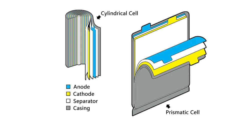
    Pre-cut anode sheets, separators, and cathode sheets are wound in a defined sequence around a fixed mandrel, compressed into cylindrical, elliptical, or prismatic shapes. The winding electrodes are then housed in cylindrical or prismatic metal casings. Electrode dimensions and winding turns are determined by the battery's design capacity.

    Stacking and Winding Process

    2. Electrochemical Performance Comparison


    Internal Resistance:

    Stacking cells exhibit lower internal resistance due to parallel welding of multiple tabs, shortening lithium-ion migration paths. This reduces heat generation during operation and slows initial energy density degradation. In contrast, winding cells rely on single-tab current output, resulting in higher internal resistance.


    Cycle Life:

    Stacking cells demonstrate superior thermal management, enabling uniform heat distribution. Winding cells exhibit gradient structural and mechanical properties, leading to uneven heat dissipation and localized temperature gradients. This accelerates capacity fade and reduces cycle life in wound cells.


    Electrode Mechanical Stress:

    Stacking electrodes experience uniform mechanical stress without localized concentration, minimizing material layer damage during charge/discharge cycles. Winding cells develop stress concentrations at bending points, increasing risks of structural failure, short circuits, and lithium plating under electrical load.


    Rate Capability:

    Stacking cells achieve enhanced rate performance due to parallelized current pathways from multiple electrode layers, enabling faster high-current discharge. Winding cells face limitations from single-tab architecture.


    Energy Density Design:

    Stacking optimizes packaging space utilization, maximizing active material loading for higher energy density. Winding cells suffer from space inefficiency due to curved electrode geometry and dual-layer separator configurations.


    3. Process Advantages


    Stacking Process:

    • High Volumetric Capacity: Superior space utilization enables higher capacity within equivalent volumes.
    • Elevated Energy Density: Higher discharge voltage plateau and volumetric capacity.
    • Design Flexibility: Customizable electrode dimensions support non-standard cell geometries.

    Stacking and Winding Process

    Winding Process:

    • Simplified Spot Welding: Requires only two welding points per cell.
    • Production Scalability: Simplified two-electrode configuration streamlines process control.
    • Efficient Slitting: Single anode/cathode slitting operation reduces defect rates.


    4. Process Limitations


    Stacking Process:

    • Cold Welding Risks: Multi-tab lamination increases susceptibility to incomplete welds.
    • Low Equipment Efficiency: Domestic stacking machines operate at 0.8 sec/layer vs. 0.17 sec/layer for imported counterparts.

    Winding Process:

    • High Polarization Losses: Single-tab design exacerbates internal polarization, degrading rate performance.
    • Thermal Management Challenges: Difficulty implementing inter-cell thermal isolation increases thermal runaway risks.
    • Thickness Variability: Structural inhomogeneity causes uneven thickness at tabs, separator edges, and cell sides.


    5. Conclusion


    Stacking and winding processes present distinct trade-offs in lithium battery manufacturing. Stacking excels in energy density, thermal performance, and design flexibility, making it ideal for new energy vehicles and energy storage systems. Winding offers cost efficiency and scalability advantages for high-volume applications like consumer electronics. Continuous technological advancements will further optimize both methodologies, driving innovation across the lithium battery industry.


    TOB NEW ENERGY provides a full set of battery production line solutions, We can customize different processes (stacking process, winding process) pouch cell lab line, pilot line, production line according to clients requirement.

  • The Impact of Formation Conditions on Battery Performance

    In the manufacturing process of lithium-ion batteries, formation is a critical procedure. This article discusses the impact of formation conditions (e.g., formation current, formation voltage, formation temperature, and external pressure) on battery performance, including internal resistance, capacity, and cycle life. TOB NEW ENERGY provides battery formation machine of various specifications to meet the production needs of battery laboratory research and battery production lines.

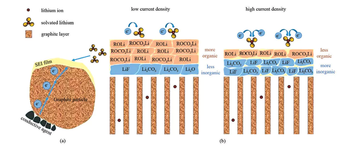
    Formation refers to the initial charging process after electrolyte injection and rest, during which the solid electrolyte interphase (SEI) layer is formed. Variations in formation protocols result in slightly different SEI layers. The morphology of the SEI layer directly affects cell performance, such as rate capability, high-voltage stability, and particularly cycle life.

    Below is a detailed analysis of how formation conditions influence cell performance:


    1. Formation Current

    Studies show that lower current densities facilitate the formation of a robust SEI layer. The SEI formation involves two stages: nucleation and growth. High current densities accelerate nucleation, leading to a porous SEI structure with poor adhesion to the anode surface. Conversely, low current densities slow nucleation, producing a denser SEI layer. However, a porous SEI can better infiltrate the electrolyte, resulting in higher ionic conductivity compared to SEI formed under low current densities.

    Traditional low-current pre-charging methods help form a stable and dense SEI, but prolonged low-current charging increases SEI impedance, negatively impacting rate capability and cycle life. Additionally, low-current formation prolongs production time, reducing manufacturing efficiency. To address this, a stepwise current formation protocol during the constant-current (CC) phase has been proposed. This approach reduces polarization, improves charge capacity, shortens formation time, and enhances efficiency.

    battery formation

    Figure 1(a) SEI formation on graphite surfaces during formation and (b) the effect of formation current density on SEI structure.


    2. Formation Voltage

    Different formation voltages significantly affect electrode surface conditions, internal resistance, and cycle performance. For example, a study comparing cutoff voltages of 3.5 V and 4.2 V found that a 4.2 V cutoff yielded higher charge capacity but 4.1% lower charge-discharge efficiency than 3.5 V. Batteries formed at 4.2 V exhibited higher electrode resistance and faster cycle degradation.

    3. State of Charge (SOC)

    SOC is a critical parameter in formation optimization. Coupled with charge/discharge voltage, varying SOC levels during aging induce different degrees of reactivity, altering SEI properties and ultimately battery performance. Experimental results indicate that 25% SOC leads to higher impedance and lower capacity retention before and after aging. The optimal protocol involves charging to 100% SOC, discharging to 25% SOC (i.e., maintaining 75% SOC), followed by aging at room temperature. This method achieves the highest initial discharge capacity and capacity retention.


    4. Formation Temperature

    For polymer lithium-ion batteries, high-temperature formation promotes more complete SEI formation and enhances separator wettability, reducing gas generation. However, low-temperature formation favors slower lithium salt reduction, enabling ordered and dense SEI deposition, which extends cycle life. While high-temperature SEI layers exhibit higher ionic conductivity, their instability due to accelerated dissolution and solvent co-intercalation worsens cycle performance. Most manufacturers adopt high-temperature aging (30–60°C) to improve cycle and storage performance.


    5. External Pressure

    Gas generation during formation increases the distance between electrodes, lengthening Li-ion transport paths and raising impedance, thereby reducing capacity. Applying moderate pressure eliminates gas, ensures tight electrode contact, minimizes deformation, and improves formation capacity, rate capability, and cycle life. Post-mortem analysis reveals that insufficient pressure causes lithium plating on the anode, while optimal pressure prevents such defects.


    Summary:

    The formation process plays a decisive role in lithium-ion battery performance. Optimizing formation current, voltage, temperature, and external pressure is crucial for enhancing battery properties. However, individual parameter adjustments yield limited improvements. A holistic optimization strategy is essential to maximize battery performance.

  • The Role of Ni, Co, Mn, and Al in Li-ion Battery Ternary Cathode Materials

    Lithium-ion batteries (LIBs) are the powerhouse of modern electronics and electric vehicles (EVs), and their performance hinges on the cathode materials. Among these, ternary cathode materials such as NCM (Nickel-Cobalt-Manganese oxides) and NCA (Nickel-Cobalt-Aluminum oxides) dominate due to their balanced energy density and stability. However, varying the ratios of nickel (Ni), cobalt (Co), manganese (Mn), or aluminum (Al) profoundly impacts their electrochemical behavior. Let’s dissect the roles of each element and how their proportions influence battery performance.


    1. Nickel (Ni): The Energy Density Booster

    Key Functions

    • High Capacity: Nickel is the primary contributor to capacity. It undergoes redox reactions (Ni²⁺ ↔Ni³⁺ ↔Ni⁴⁺) during charge/discharge, enabling the extraction and insertion of lithium ions. Higher nickel content increases the material’s specific capacity (e.g., NCM811 delivers ~200 mAh/g vs. NCM111’s ~160 mAh/g).
    • Voltage Profile: Nickel-rich cathodes exhibit a higher average discharge voltage (~3.8 V), directly boosting energy density.
    • Structural Challenges:
      • Phase Transitions: At high nickel levels (>80%), layered structures (e.g., α-NaFeO₂-type) tend to transform into disordered spinel or rock-salt phases during cycling, causing irreversible capacity loss.
      • Cation Mixing: Ni²⁺ions (ionic radius ~0.69Å) may migrate into Li⁺sites (0.76Å), blocking lithium diffusion pathways and accelerating degradation.

    Impact of Nickel Content

    • High-Ni Cathodes (e.g., NCM811, NCA):
      • Pros: Energy density up to 300 Wh/kg, ideal for EVs requiring long driving ranges.
      • Cons: Poor thermal stability (thermal runaway starts at ~200°C), shorter cycle life (~1,000 cycles at 80% capacity retention).
    • Mitigation Strategies: Surface coatings (e.g., Al₂O₃, LiPO₄), doping with Mg/Ti to stabilize the structure.


    2. Cobalt (Co): The Structural Stabilizer

    Key Functions

    • Structural Integrity: Co³⁺suppresses cation mixing by maintaining strong Co-O bonds, preserving the layered structure.
    • Electronic Conductivity: Co enhances electron transport, reducing internal resistance and improving rate capability.
    • Ethical and Economic Issues: Cobalt is expensive (~$50,000/ton) and linked to unethical mining practices in the Democratic Republic of Congo (DRC), driving efforts to eliminate it.

    Impact of Cobalt Content

    • High-Co Cathodes (e.g., NCM523):
      • Pros: Excellent cycle life (>2,000 cycles), stable voltage output.
      • Cons: High cost, limited sustainability.
    • Low-Co/Co-Free Alternatives:
      • Manganese Substitution: Mn or Al replaces Co in NCMA (Ni-Co-Mn-Al) cathodes.
      • LiNiO₂-Based Materials: Pure nickel cathodes are being explored but face severe structural instability.


    3. Manganese (Mn) and Aluminum (Al): Stability Enhancers

    Manganese in NCM

    • Thermal Stability: Mn⁴⁺forms strong Mn-O bonds, delaying oxygen release at high temperatures (>250°C for NCM vs. <200°C for high-Ni systems).
    • Cost Reduction: Manganese is abundant and cheap (~$2,000/ton), lowering material costs.
    • Drawbacks: Excess Mn (>30%) promotes spinel phase formation (e.g., LiMn₂O₄), reducing capacity and voltage.

    Aluminum in NCA

    • Structural Reinforcement: Al³⁺(ionic radius ~0.54Å) occupies transition metal sites, minimizing cation mixing and improving cycle life.
    • Safety Boost: Al-O bonds are highly stable, reducing oxygen evolution during thermal abuse.
    • Trade-offs: High Al content (>5%) degrades electronic conductivity, requiring nanosizing or carbon additives.


    4. Balancing the Elements: Popular Compositions and Trade-offs

    Material

    Ratio (Ni:Co:Mn /Al)

    Energy Density

    Cycle Life

    Thermal Stability

    Cost

    Applications

    NCM111

    1:1:1

    Moderate

    High

    Excellent

    Medium

    Power tools, low-cost EVs

    NCM523

    5:2:3

    Moderate-High

    High

    Good

    High

    Mid-range EVs, laptops

    NCM811

    8:1:1

    Very High

    Low

    Poor

    Low

    Premium EVs (Tesla, NIO)

    NCA

    8:1.5:0.5 (Ni:Co:Al )

    Very High

    Moderate

    Moderate

    High

    Tesla Model S/X


    5. Future Trends and Innovations

    High-Ni, Low-Co Systems

    • Goal: Achieve >350 Wh/kg energy density while minimizing cobalt (e.g., NCM9½½, NCMA).
    • Challenges: Managing Ni-induced degradation via atomic-layer deposition (ALD) coatings or gradient structures (core-shell designs).

    Solid-State Batteries

    • Ternary materials paired with solid electrolytes (e.g., Li₇La₃Zr₂O₁₂) could suppress dendrites and enhance safety.

    Sustainability Initiatives

    • Recycling: Recovering Ni/Co from spent batteries (e.g., hydrometallurgy) to reduce reliance on mining.
    • Cobalt-Free Cathodes: Mn-rich LNMO or LiFePO₄for cost-sensitive applications.

    Conclusion

    The chemistry of ternary cathode materials is a delicate dance between energy density, longevity, safety, and cost. Nickel drives capacity but destabilizes the structure, cobalt anchors stability at a high price, while manganese and aluminum offer affordable reinforcement. As the industry marches toward Ni-rich, Co-low systems, breakthroughs in material engineering and recycling will be key to powering the next generation of EVs and renewable energy storage.

    Learn More About NCM Cathode Materials and NCA Cathode Materials for Lithium ion Battery Research and Manufacturing

  • Analysis of insulation of ammonia pipeline using electric heating system

    As an important chemical raw material and refrigerant, the stability of ammonia pipeline transportation system is directly related to production safety and efficiency. In low temperature environment, ammonia is easy to liquefy, water in the pipeline freezes or forms ammonia corrosion, which may lead to blockage, leakage and other risks. With its precise temperature control, explosion-proof and corrosion-resistant characteristics, the electric heating system has become a more suitable solution for antifreeze insulation of ammonia pipelines.

    Self Regulating Heating Cable


    Why does ammonia pipeline need electric heating system insulation?
    Prevent liquid ammonia condensation and ice blockage: The boiling point of ammonia at standard atmospheric pressure is -33.34°C. When the pipeline temperature is lower than this value, gaseous ammonia will liquefy into liquid ammonia, causing flow meter failure and valve blockage. Electric heating maintains the pipeline temperature above 0°C to ensure that ammonia is transported stably in gaseous form.
    Inhibit ammonia corrosion and freezing: If there is water in the pipeline, it will react with ammonia to form ammonia water at low temperature, and the freezing point will rise. However, ammonia water is highly corrosive and will accelerate the corrosion of pipelines and welds. Electric heating eliminates condensed water through temperature control and slows down the corrosion process.
    Ensure the stability of the emergency system: When ammonia leaks, the sprinkler system needs to start quickly to dilute the concentration. If the fire water pipe freezes, it will delay the disposal and may cause an accident. Electric heating ensures that firefighting and pressure relief facilities are available at any time.
    Adapt to harsh environments and energy-saving needs: Winter temperatures in the north can drop to -40°C, and the electric heating system can meet the requirements with relatively high thermal efficiency.
    Antifreeze and heat preservation of ammonia pipelines are not only related to production continuity, but also the core requirements of safety and compliance. Through material innovation and intelligent control, the electric heating system has built a protection system for ammonia transportation from antifreeze, anticorrosion to emergency linkage.
  • Analysis of the application of electric heating tape insulation in food processing equipment

    In the food processing industry, temperature control is the core link to ensure product quality, production efficiency and food safety. Whether it is chocolate tempering, oil delivery, or fermentation tank insulation, equipment temperature fluctuations may cause raw materials to solidify, microbial growth or process failure. With precise temperature control and compliance design, electric heating tape has become an ideal choice for food processing equipment insulation.

    In the food processing industry, temperature control is the core link to ensure product quality, production efficiency and food safety. Whether it is chocolate tempering, oil delivery, or fermentation tank insulation, equipment temperature fluctuations may cause raw materials to solidify, microbial growth or process failure. With precise temperature control and compliance design, electric heating tape has become an ideal choice for food processing equipment insulation.
  • Bifacial Solar Panel Ground Mounting System

    Bifacial Solar Panel Ground Mounting is design with no shading under the Bifacial Solar Panel array, this ensures the bifacial panel can capture sunlight from both rear and front side of panel.  The special rail designs ensure more strength to hold panel, it is quick and durable mounting systems with cost effective for the Bifacial Solar Panel.


    The bifacial solar panel mounting systems is quick and easy solutions, all the components are pre-assembled onfactory, less work to do on sites, just few components as below. It is quite easy to install If come with ground screw. There are two foundation solutions for the mounting systems, ground screw and concrete foundation.


    Structure overview


    Back side view


    Front side view


    TECHNICAL INFORMATION

    Install site: Open Field

    Module Arrangement: Landscape

    Tilt Angle: 0-65 deg

    Main Material: Aluminum 6005 T5


    If you need this product, please feel free to contact us. Hope can work with you to cut your cost and reach mutual benefit.  (sales7@landpowersolar.com)